
CCE Cluster Network Description and Planning
Overview
Effective cluster network planning ensures it meets the demands of service development. This document introduces the roles of various network addresses within the CCE Kubernetes cluster in Baidu AI Cloud's Virtual Private Cloud (VPC) environment, along with methods for planning the address fields.
Concept of cluster network
Cluster networks include the following: node network, container network, and service network, each with specific functionalities.
Node network
The node network is the IP address within the host-assigned node network range in the cluster. When creating a cluster, you should select the subnet of the node network. For more information about the node network and subnet, please refer to Virtual Private Cloud (VPC) Subnet.
Container network
The container network is the network segment where container instance pods reside. This segment cannot be modified once the cluster has been created.
- A pod is the smallest management unit in Kubernetes, representing a unique IP within the Kubernetes network model.
- The container network consists of IP addresses allocated to pods within the cluster's container network range. Baidu AI Cloud CCE offers three main categories of user-defined private network segments—10.x.x.x, 192.x.x.x, and 172.x.x.x—as container networks. It also automatically calculates the maximum number of cluster nodes allowed based on the configured maximum number of pods operable by a single node. Note: Due to a 200-limit quota on VPC route tables.
Service network
Services in a Kubernetes cluster do not have a physical presence in the actual network and exist as purely virtual IP network segments.
- On cluster nodes, kube-proxy forwards service addresses to corresponding backend pods using iptables or ipvs.
- The service address field must not overlap with the container network or node network.
- The service address is used in the Kubernetes cluster and cannot be used outside the cluster. Currently, the service address hasn't been exposed to users for selection. CCE selects an address which doesn't conflict with the container network and the node network as service network address from 172.[16-31].0.0/16.
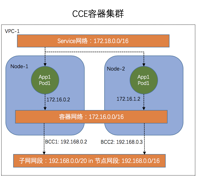
K83S Cluster CCE network architecture diagram
The K83S Cluster CCE network architecture diagram is as follows, including node network, container network and service network.
Descriptions of CCE container network
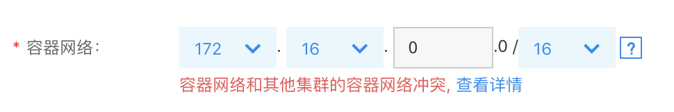
When configuring the container network in CCE, address conflicts are checked. If conflicts are identified, detailed information is available to pinpoint conflicting addresses or routes. Users can then opt to use the recommended container network. If no recommendation is available, it means the current VPC has no suitable container network, and creating a new VPC to deploy the K83S Cluster CCE is advisable.
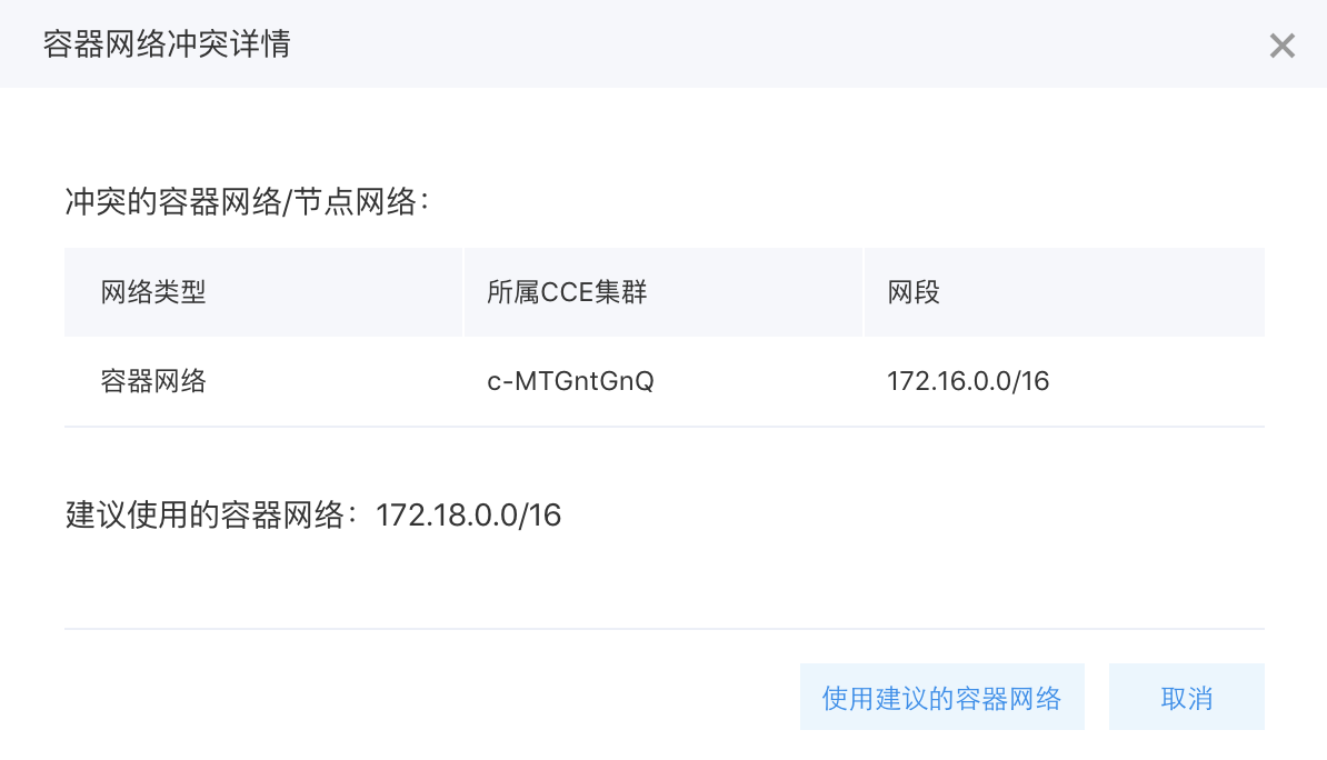
Select to view details:
You can view the conflict details of the container network, and select to use the recommended container network.
There are the following points in checking the container network conflicts:
- Verify that the container network does not conflict with the node network.
- Ensure there are no conflicts between the current container network and the container networks of other clusters within the same VPC.
- Confirm that the current container network does not conflict with existing VPC routes in the cluster’s VPC. Specifically, first check if the source address is 0.0.0.0/0, and, if so, proceed to compare the destination address.
K83S Cluster CCE network planning
To facilitate communication between containers, each container network segment is added to the route table during cluster creation in CCE. To prevent network segment conflicts, VPC and container network segments must be allocated wisely.
Verify that the VPC node subnet network does not overlap with the container network. For instance, if the VPC node subnet is set to 172.16.0.0/16 and the container network is also set to 172.16.0.0/16, a conflict warning will appear during cluster creation, prompting the use of a recommended container network.
Process and example of K83S Cluster CCE network creation
Below is a detailed step-by-step example demonstrating the creation process of a K83S Cluster CCE within an entire VPC.
Step1: Create a VPC network
- Sign in to VPC Console
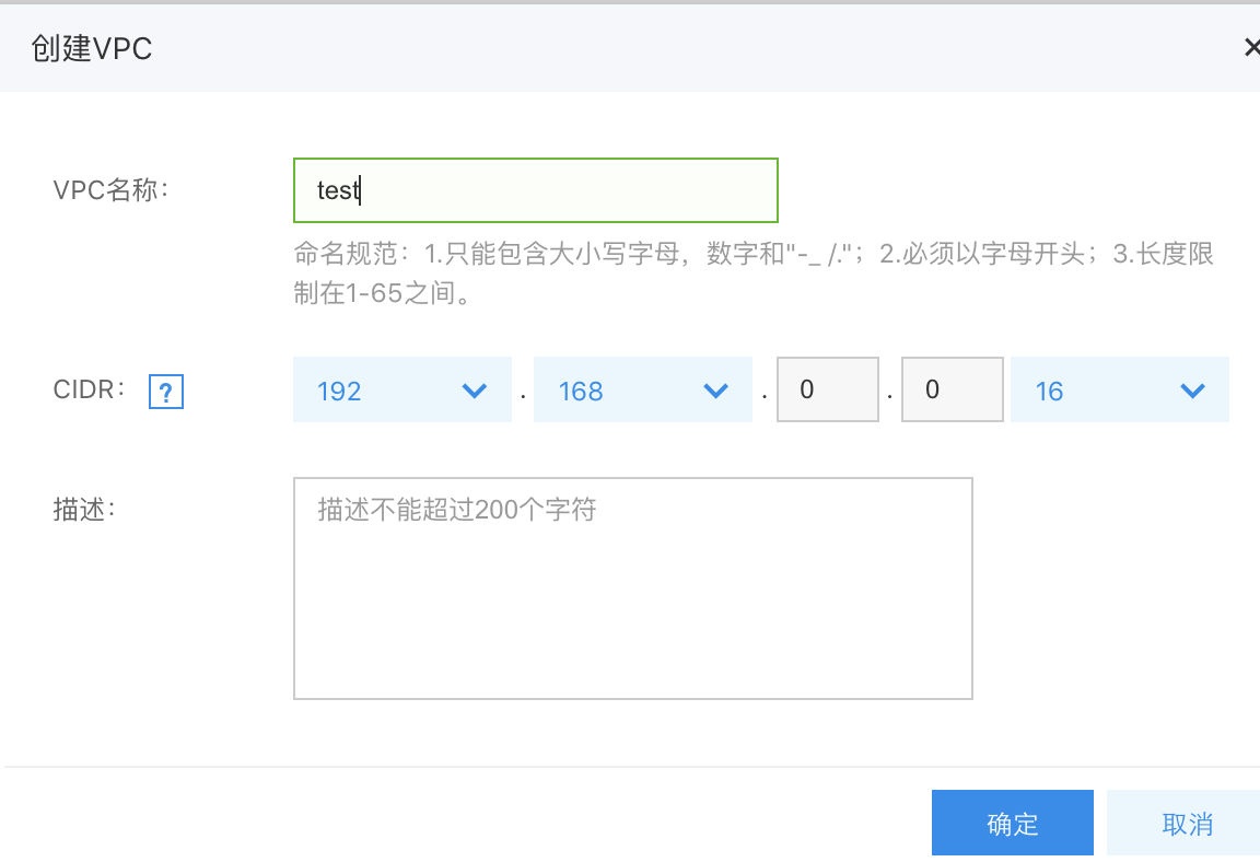
- Click Create VPC.
- Select the VPC CIDR and click OK.
In this example, select VPC network of 192.168.0.0/16 to avoid conflicting with the container network.
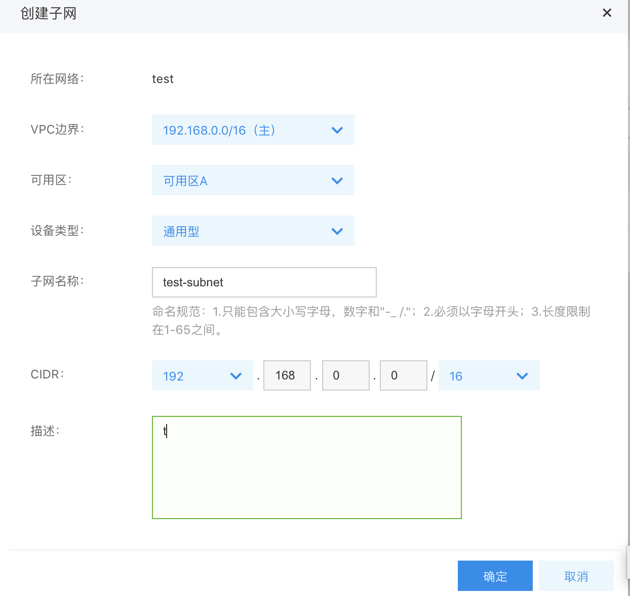
Step2: Create a subnet in VPC network
- Once the VPC is created, define a subnet within the VPC, and select its CIDR.
- Select the general-purpose or NAT-dedicated device type. In case of any Internet access requirements, refer to CCE Practice of Accessing Public Network
.
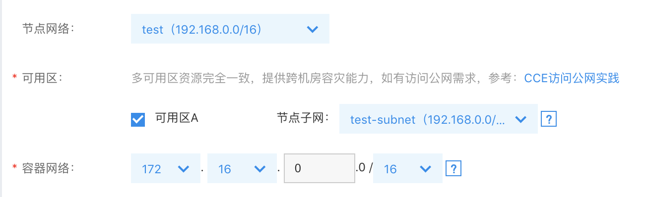
Step3: Create K83S Cluster CCE
- Sign in to CCE Console
- Click on "Create Cluster.\
- Select the node network and the node subnet which are just created. In case of any container network conflicts, click to view the details, and use the recommended container network.
Step4: Verify node IP
Once the container cluster is successfully created, confirm the cluster IP.
- In the CCE Console, go to "Cluster List" and select the newly created cluster.
- After accessing the cluster details, navigate to "Node Management" >> "Worker" from the left menu.
- Check whether the node intranet IP belongs to the node subnet selected during cluster creation.
It is shown in the figure below:

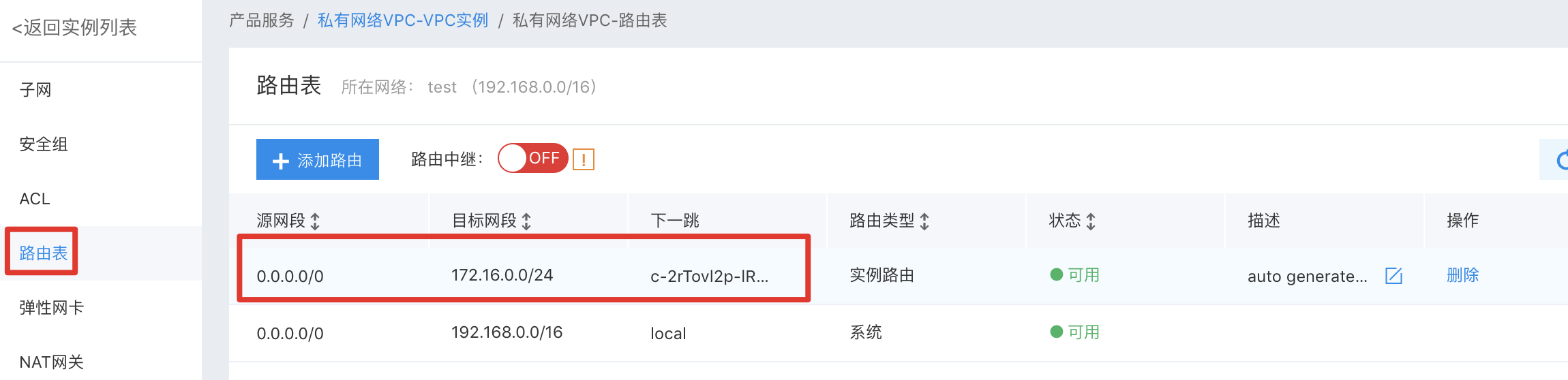
Step5: Verify the route table
- Sign in to VPC Console
- Choose the newly created VPC.
- Click the left navigation bar and select the route table. You can view the route information for the added network segment of 172.16.x.0/24.The next hop is the ID of BCC instance.
It is shown in the figure below:
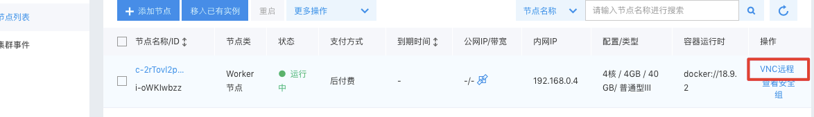
Step6: Verify pod IP
Finally, check if the IP assigned to the pod is correct.
- In the CCE Console, go to "Cluster List" and select the newly created cluster.
- After accessing the cluster details, navigate to "Node Management" >> "Worker" from the left menu.
- Select VNC to remotely log in to the cluster node.
- Enter username and password, then execute:
kubectl get pods -n kube-system -o wideIt is as shown in the figure below: You can see the container-assigned IP is 172.16.0.x, which belongs to the container network selected during cluster creation.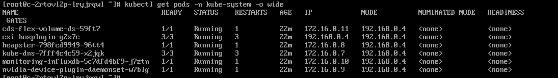
If the above verification is successful, it means a cluster in the VPC network has been successfully created.