Traffic Forwarding Configuration for Containers in Peering Connections Scenarios
This document explains how to configure VPC routing for cross-VPC clusters in peering connection scenarios, enabling connectivity between clusters at both the node and container levels.
Prerequisites
-
Peering connections have been created
Peering connection provides users with VPC-level network interconnection services, and enables traffic exchange between/among different virtual networks. This document assumes that users have already established peering connections and VPC endpoints. For specific creation steps, refer to Peering Connections
-
Network segments of the cluster do not conflict with each other
Three key network segments in a k8s cluster are the node network segment, the container network segment, and the ClusterIP network segment. To enable cross-VPC interconnection between two clusters at the node and container levels, ensure there are no conflicts between any two network segments across the k8s clusters.
-
Container traffic egressing nodes without SNAT
Since VPC network segments are all private IP segments, such as 10.0.0.0/8, 172.16.0.0/12, and 192.168.0.0/16, under CCE's default configuration, container traffic exiting nodes does not perform SNAT for private network segments.
Configuration case
Environment overview
Taking two clusters as an example for configuration explanation: Cluster A and Cluster B, with specific parameter configurations listed in the table below.
No network segment conflicts exist between Cluster A and Cluster B, meeting the requirements for cross-VPC cluster interconnection and enabling subsequent configurations.
| Cluster | A | B |
|---|---|---|
| Region | gz | sz |
| Node network segment | 192.168.0.0/16 | 10.0.0.0/8 |
| Container network segment | 172.16.0.0/16 | 172.17.0.0/16 |
| ClusterIP network segment | 172.30.0.0/16 | 172.31.0.0/16 |
Configure the VPC route.
After establishing peering connections and VPC endpoints, users can configure VPC routing. Routes need to be set up in the VPCs of both clusters. For this example, users need to configure 4 routes in each VPC as follows:
- Route from the node of this cluster to the node of the peer cluster
- Route from the node of this cluster to the container of the peer cluster
- Route from the container of this cluster to the node of the peer cluster
- Route from the container of this cluster to the container of the peer cluster
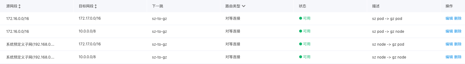
The configuration results are as follows:
Route of the VPC where Cluster A is located:
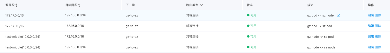
Route of the VPC where Cluster B is located: