
Connecting On-Premises IDC to Cloud VPC via Multi-Line ECMP (Dynamic Routing)
Overview
This document explains how to seamlessly integrate the Express Tunnel (ET) application to connect a local Internet Data Center (IDC) to the cloud using BGP multi-line ECMP, enabling interconnection with an on-cloud Virtual Private Cloud (VPC).
Requirement scenarios
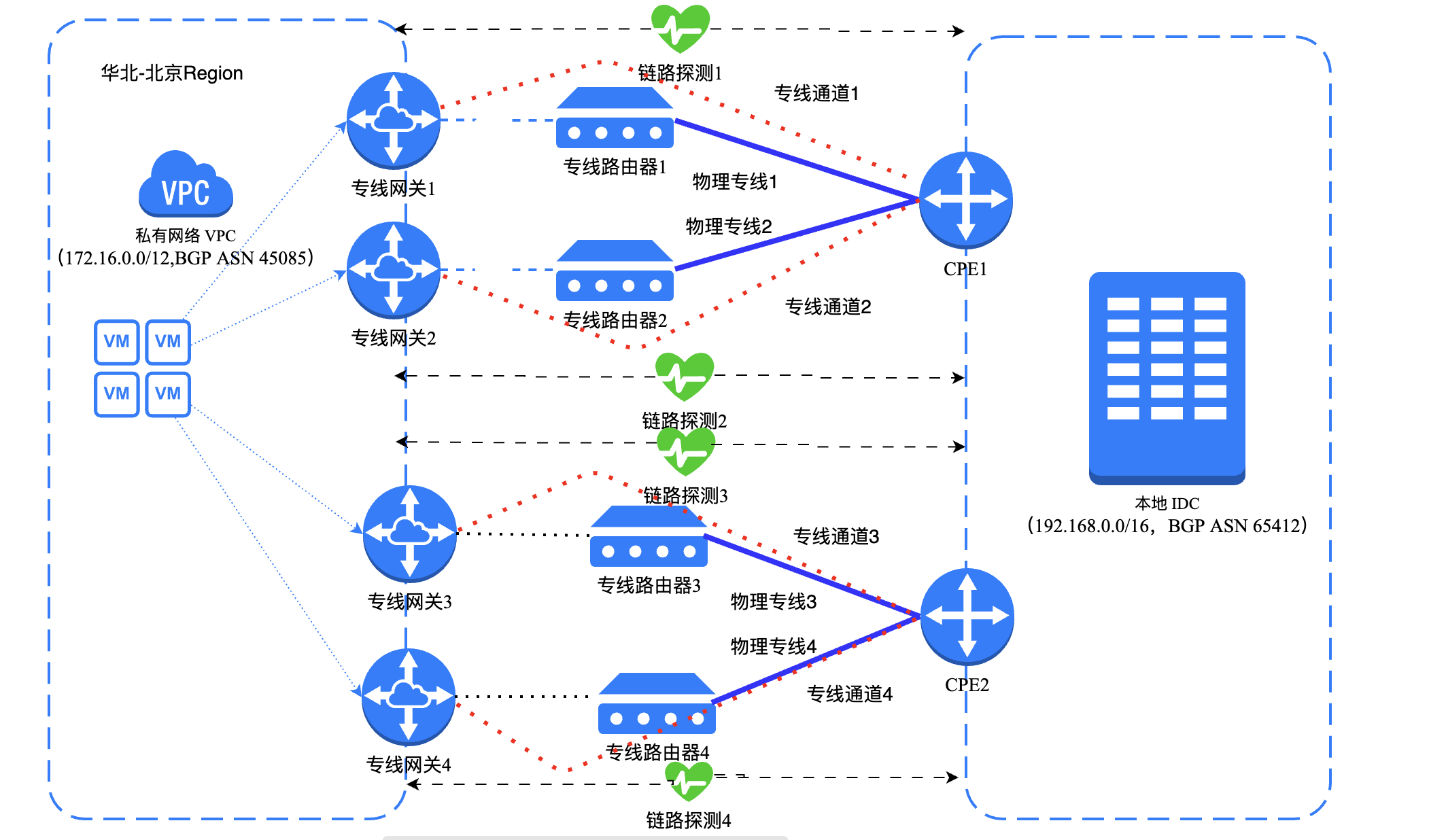
Using the scenario demonstrated in the diagram, this document illustrates how a local IDC can connect to Baidu AI Cloud through the BGP routing method via the Express Tunnel's dedicated channel for load redundancy. Typically, four physical dedicated lines simultaneously forward traffic. If one physical line experiences a connection failure, its traffic is redistributed and balanced across the remaining lines to ensure uninterrupted service.
Solution overview
This document takes the example shown in the diagram to explain how a local IDC accesses Baidu AI Cloud using ECMP dedicated lines.
A Beijing-based enterprise operates a local IDC (VPC network segment: 192.168.0.0/16) and has established a Virtual Private Cloud (VPC) (network segment: 172.16.0.0/12) in Baidu AI Cloud's North China-Beijing Region. To eliminate single points of failure, the enterprise must apply for two physical dedicated lines from two different carriers. Each carrier's pair of dedicated lines connects to the same Express Tunnel POP point in Baidu AI Cloud, ensuring simultaneous traffic forwarding across all four physical lines.
| Dedicated channel configuration item | Dedicated Channel 1 (Dedicated channel of physical dedicated line 1) | Dedicated Channel 2 (Dedicated channel of physical dedicated line 2) | Dedicated Channel 3 (Dedicated channel of physical dedicated line 3) | Dedicated Channel 4 (Dedicated channel of physical dedicated line 4) |
|---|---|---|---|---|
| VLAN ID | 0 | 0 | 0 | 0 |
| IPv4 cloud network interconnection IP | 9.39.39.1 | 9.39.39.5 | 9.39.39.9 | 9.39.39.13 |
| IPv4 IDC interconnection IP | 9.39.39.2 | 9.39.39.6 | 9.39.39.10 | 9.39.39.14 |
| IPv4 subnet mask | 30 | 30 | 30 | 30 |
| Routing protocol | Dynamic routing | Dynamic routing | Dynamic routing | Dynamic routing |
Configuration steps
Environment preparation
- Users have already set up a VPC in Baidu AI Cloud's North China-Beijing Region and have deployed related services using Baidu Cloud Compute (BCC) and other cloud resources within the VPC.
- Users are familiar with the security group rules applied to BCC instances in the VPC and have verified that these rules allow mutual access between the local IDC and BCC instances on the cloud.
- Before purchasing physical dedicated lines, users have reviewed the applicable billing rules. As this document requires four physical dedicated lines, users must submit four port applications.
Configuration process
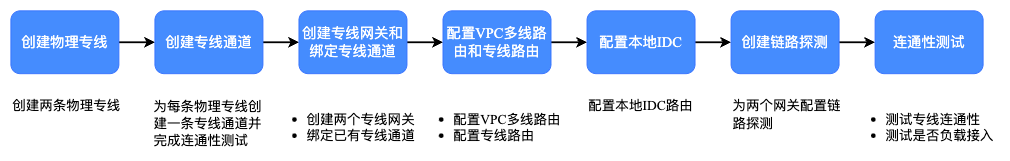
Please execute configurations according to steps specified in the document, and proceed only after verifying the completion of the current step
Step I: Create a physical dedicated line
- Log in to the Baidu AI Cloud console.
- Go to Product Service, select Express Tunnel (ET), click on Physical Dedicated Line, and choose Apply for Physical Dedicated Line.
- On the Create Dedicated Channel page, configure the required parameters and click OK after confirming there are no mistakes.
| Configuration | Description |
|---|---|
| Dedicated line name | Assign a name to the physical dedicated line. In this document, the name "Physical Dedicated Line 1" has been selected. |
| Access point mode | Choose the access point search mode. The system currently supports standard mode and map mode. |
| Region | Select the region where the IDC and VPC are located. This document chooses the North China-Beijing region. |
| Description | Provide a description for the physical dedicated line. |
| Access point | Make selections based on the actual situation. For further details, refer to xxx. In this document, Beijing-Beijing-Daxing-A and Beijing-Beijing-Daxing-B access points are used. |
| Physical Line ISPs | Choose a dedicated line operator. Following this, please purchase dedicated line access through the carrier of the selected access point's data center. |
| Physical port specifications | Specify the dedicated port configuration. |
| Peer address | Input the IDC's address. |
| Purchase period | Set the duration for service usage. |
| Auto-renewal | Decide whether to enable the auto-renewal option. |
- Description:
- After completing the configuration steps, submit the order to proceed to the payment page.
- After successfully completing the payment, go back to the physical dedicated line console interface, where the status will show "Pending Approval." Reach out to the Baidu AI Cloud team for review and approval.
- Once the Baidu AI Cloud team approves, the physical dedicated line status will update to "Available," and you will receive an email notification confirming the successful creation of Physical Dedicated Line 1.
- Repeat Step I to set up Physical Dedicated Lines 2, 3, and 4.
Step II: Create dedicated channel
- When the physical dedicated line becomes available, click on Dedicated Channel, and then choose Add Dedicated Channel under the dedicated channels section of the account.
- On the Create Dedicated Channel page, configure the required parameters and click OK after confirming there are no mistakes.
| Configuration | Description |
|---|---|
| Physical dedicated line ID | Assign a name to the physical dedicated line. In this document, the name "Physical Dedicated Line 1" has been selected. |
| Channel name | Specify a name for the dedicated channel. |
| Allocation object | Select a user for the dedicated channel. In this document, the current account is chosen. |
| VLAN ID | Input the VLAN ID for the dedicated channel. In this document, the value 0 is used, indicating that the physical dedicated line is exclusively assigned to you. |
| Cloud network interconnection IP | Enter the IPv4 address and subnet mask for the ingress gateway from the VPC to the local IDC. Here, the address 9.39.39.1 with a mask of 30 is used. |
| IDC interconnection IP | Provide the IPv4 address and subnet mask for the ingress gateway from the local IDC to the VPC. The address 9.39.39.2 with a mask of 30 is used in this document. |
| Routing protocol | Choose whether the routing protocol will be static or dynamic (BGP). The extra parameters marked with * in the table below will only appear if dynamic routing is selected. In this document, dynamic routing is used. |
| *BGP ASN | Input the BGP AS number for the IDC side. The value used here is 65412. |
| *BGP key | Provide the key essential for establishing the BGP peer connection. |
| Description | Add a description for the dedicated channel. |
- Description:
- After completing the configuration, the status of the dedicated line channel on the console will display "Pending Application." Contact the Baidu AI Cloud team for review and approval.
- After receiving approval from Baidu AI Cloud staff, the dedicated line channel status will change to "Available." At this point, you can test the connectivity between the IPs of the cloud network interconnection and the local IDC interconnection. If dynamic routing was chosen in the earlier steps, verify that the BGP peers have successfully established connections.
- Repeat Step II to create dedicated channels for Physical Dedicated Lines 2, 3, and 4 in sequence.
Step III: Create a dedicated gateway and bind a dedicated channel
- Start by creating a VPC in the desired Region. In this document, a VPC has been created in the North China-Beijing Region of Baidu AI Cloud, and associated cloud resources, like BCC cloud servers, have been deployed within the VPC for related services.
- Once the dedicated channel is active, click on Dedicated Gateway. Alternatively, log in to the VPC Management Console and select Dedicated Gateway under Network Connections.
- From the dropdown menu at the top of the page, choose the desired cloud VPC, and then click Create Dedicated Gateway.
- On the Create Dedicated Gateway page, configure the parameter details, and click OK after ensuring that there are no errors.
| Configuration | Description |
|---|---|
| Virtual private cloud | Choose the VPC on the cloud where the new dedicated gateway will be deployed. The VPC selected in the previous dropdown is set as the default but can be changed if needed. |
| Gateway name | Set the name for the dedicated gateway instance. In this document, "Dedicated Gateway 1" has been chosen. |
| Egress bandwidth | Select the outbound cloud bandwidth according to your actual service requirements. |
| Bind physical dedicated line | Decide whether to bind a physical dedicated line. In this document, a physical dedicated line is bound. Choose the line ID for Physical Dedicated Line 1 from the dropdown menu, then select the corresponding dedicated channel ID. |
| Description | Provide a description for this dedicated gateway. |
| Resource group | Select the resource group that the dedicated gateway will belong to. After successfully creating the dedicated gateway, you can also locate the target instance and click "Add Resource" in the Resource Group column to finalize the process. |
- Description:
- Once the configuration is complete, the dedicated gateway's status on the console will change to "available." Repeat Step 3 to create Dedicated Gateways 2, 3, and 4 sequentially, binding each to Physical Dedicated Lines 2, 3, and 4 respectively.
Step IV: Create a dedicated gateway and bind a dedicated channel
- Configure routes in the VPC Route Table and on the Dedicated Channel Details page. Carefully review and verify this step, as any missing configuration could disrupt link connectivity.
- Configure the VPC multi-line routing
- Log in to the VPC Management Console and select "Route Table" under the Virtual Private Cloud (VPC) section.
- Use the dropdown at the top of the page to select a cloud VPC, and click on the corresponding route table name.
- Navigate to the VPC route interface and click "Add Route."
- In the "Add Route" interface, configure the necessary parameters and click "Confirm" after verifying them.
| Configuration | Description |
|---|---|
| Segment type | Choose to add IPv4 or IPv6 routing. IPv4 routing is selected in this document. |
| Source network segment | Select a subnet within the VPC or input a custom source network segment. In this document, "172.16.0.0/12" is used. |
| Destination segment | Enter the destination network segment. This document uses "192.168.0.0/16." |
| Route type | Choose the route type. For dedicated gateway routing, you can select single-line or multi-line routing. In this document, the "Dedicated Gateway" option is chosen, followed by multi-line routing. Fields marked with * in the table below will appear only when multi-line routing is selected. |
| *Multi-Line mode | Decide on the cloud access mode for the dedicated line, which can be either active-standby or load balancing (e.g., ECMP). In this document, "Load Balancer" is chosen. |
| Next-hop instance | Select the next hop for the route. In this document, "Dedicated Gateway 1" is chosen for Path 1, "Dedicated Gateway 2" for Path 2, "Dedicated Gateway 3" for Path 3, and "Dedicated Gateway 4" for Path 4. |
| Description | Provide a description for the routing entry. |
- Configure dedicated line route
- Log in to the Express Tunnel (ET) management console, go to the "Dedicated Channel" tab, select the channel ID associated with Physical Dedicated Line 1, and open the Dedicated Channel Details page.
- Go to the Route Management tab and click on Create New Route Entry.
- In the Create Route Entry interface, set the parameter details and click OK after reviewing them.
| Configuration | Description |
|---|---|
| Rule type | Choose to add IPv4 or IPv6 routing. IPv4 routing is selected in this document. |
| Destination segment | Input the destination network segment. For this example, 172.16.0.0/12 is used. |
| Next-hop instance type | Choose the appropriate instance ID. This document uses Dedicated Gateway 1 as an example. |
| Next-hop instance ID | Choose the appropriate instance ID. This document uses Dedicated Gateway 1 as an example. |
| Description | Provide a description for the routing entry. |
- After completing the configuration, repeat these steps to set up dedicated routing for Dedicated Channels 2, 3, and 4.
Step V: Configure local IDC
- Users need to finalize route settings on the local IDC side. Note that the commands will differ based on the vendor's equipment. Consult directly with the device vendor for detailed configuration commands.
- Here’s an example using configuration commands for a Cisco C-series switch.
ip route 172.16.0.0 255.240.0.0 9.39.39.1
ip route 172.16.0.0 255.240.0.0 9.39.39.5
ip route 172.16.0.0 255.240.0.0 9.39.39.9
ip route 172.16.0.0 255.240.0.0 9.39.39.13
Step VI: Create link probe
- By default, Baidu AI Cloud sends an ICMP packet every 3 seconds from the source IP address of each line to the destination address. If no response is received for three consecutive periods on a physical dedicated line, Baidu AI Cloud initiates a secondary inspection mechanism to identify the fault location. If an issue is detected, traffic will automatically reroute to another physical dedicated line.
- Log into the VPC Management Console and select Dedicated Gateway from the Network Connections section.
- In the Operations column for the appropriate dedicated gateway instance, click on Link Probe.
- Go to the Link Probe page and click the Add Rule button.
- On the Create Rules page, fill in the required parameters and click OK once all information is verified to be correct.
| Configuration | Description |
|---|---|
| Rule type | Choose either IPv4 or IPv6 link probe rules (IPv6 is optional if IPv6 is enabled for the VPC and dedicated lines). For this example, IPv4 is selected. |
| Probe subnet belonged | Scroll down to choose the subnet where the probe will be created. An unused IP address within the subnet will be allocated for the link probe. |
| Physical dedicated line ID | Select the physical dedicated line you wish to probe (this becomes available when the gateway is connected to multiple dedicated lines). |
| Dedicated channel ID | Choose the dedicated channel to be probed (you can select from multiple dedicated channels available under the physical line). |
| Probing method | The default protocol used is ICMP. |
| Source IP | The source IP address can be configured in two ways: Auto-assign (recommended): The system automatically selects an unused IP address from the specified subnet range. Custom: You can manually specify any unused IP address within the chosen subnet range. |
| Destination IP | The destination IP address can be set up in two ways: Bind channel IDC interconnection IP (recommended): The system automatically picks the designated channel IDC interconnection IP from the table above as the probe address. Custom: Users can specify the destination address as desired. |
| Health check interval | Define the time interval for sending probe packets during health checks. The unit is seconds, and you can input an integer between 1 and 60. It's recommended to set it to 3 seconds. |
| Unhealthy threshold | If consecutive health check failures surpass this threshold, the dedicated channel linked to the dedicated gateway will be considered abnormal. The threshold is an optional integer between 2 and 5, defaulting to 3 seconds. |
| Health threshold | If consecutive health check successes surpass this threshold, the dedicated channel linked to the dedicated gateway will be considered available. The threshold is an optional integer between 2 and 5, defaulting to 3 seconds. |
| Automatically generate route | A route is automatically created for connectivity testing. If disabled, users must manually add a route to the destination address for testing connectivity. Enabled by default. |
- Description:
- After completing the above configuration, wait a moment for the initialization inspection of the link probe.
- Once the link probe status is confirmed normal, repeat Step VI to create link probes for Dedicated Gateways 2, 3, and 4.
Step VII: Connectivity testing
- Description:
- After completing the above configuration, users should test the connectivity of the physical dedicated line.
- Log in to the BCC Instance within the VPC via the VPC Management Console.
- Run the ping command to verify connectivity between the BCC instance in the cloud VPC (172.16.0.0/12) and the local IDC (192.168.0.0/16). A reply message indicates a successful connection.
- Run the tracert or traceroute command to confirm that the two physical dedicated lines achieve load-balanced access through route tracking.