
Using IP Group Function to Mount Real Servers Across VPCs in Different Regions
Scenario introduction
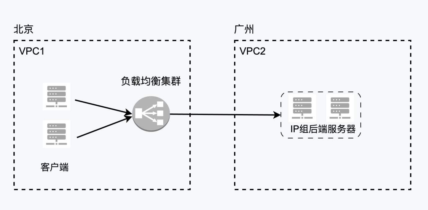
The IP group is a type of real server group for application BLB, and refers to using fixed IPs to mount real servers. In some cases, using an IP group to mount real servers across VPCs can provide a more flexible, secure, and manageable network architecture, which is suitable for complex multi-VPC environments and multi-tenant application scenarios. This document will guide you to utilize the IP group functions through practical implementation cases, using peering connections to connect two independent VPC environments across different regions.
Prerequisites
- Currently, only cross-region VPC environments connected via peering connections are supported.
- To enable relay routing between more than three VPCs interconnected through peering connections, a ticket submission is required.
Environment preparation
- For two VPCs with planned subnets, one is in Beijing and another in Guangzhou
- Purchased BLB
- Deployed real servers across other VPCs
- Peering connections purchased and deployed
Assume the deployed environment has the following IPs:
| Resource type | VPC | IP |
|---|---|---|
| Beijing VPC | VPC1 | bj_vpc_192(192.168.0.0/16) |
| Guangzhou VPC | VPC2 | gz_vpc_10(10.0.0.0/16) |
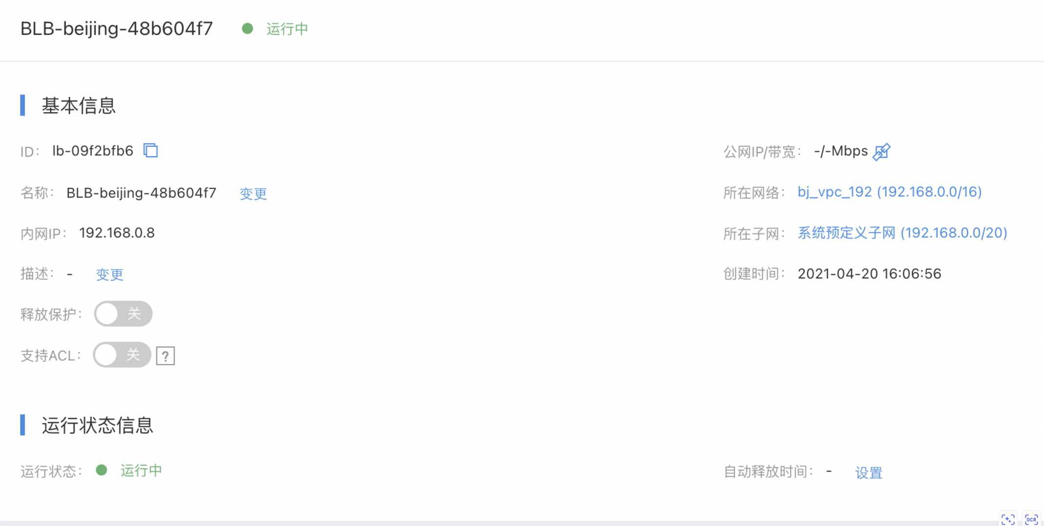
| Beijing application load balancer instance | VPC1 | 192.168.0.8 |
| Baidu Cloud Compute 1 (Guangzhou real server 1) | VPC2 | 10.100.100.5 |
| Baidu Cloud Compute 2 (Guangzhou real server 2) | VPC2 | 10.100.200.4 |
Load balancer instance and virtual machine
- Load balancer LB information
- Guangzhou real server virtual machine information
*In this scenario, the real server needs to select virtual machine instances of General Purpose Fourth Generation (g4) or higher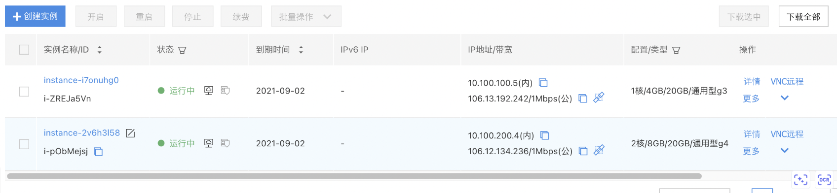
Prepare peering connections
- Beijing-side peering connections:
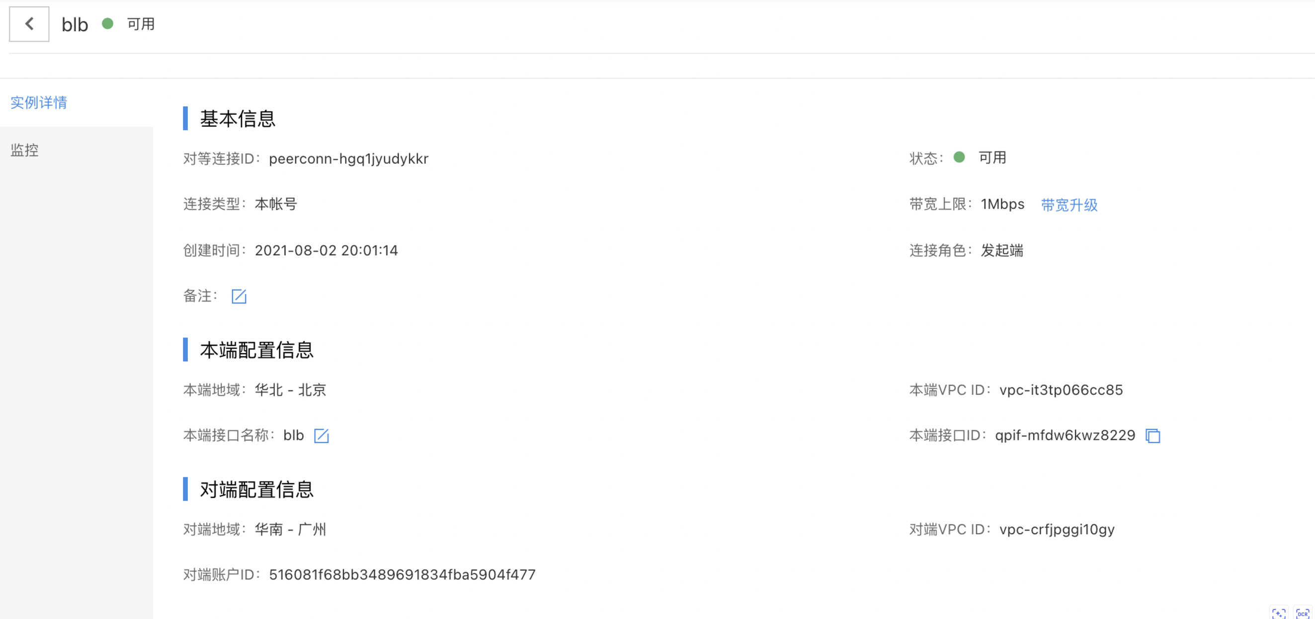
- Guangzhou-side peering connections:

Mount the real server to the load balancer backend
- Create a target group of IP group type under the Load Balancer
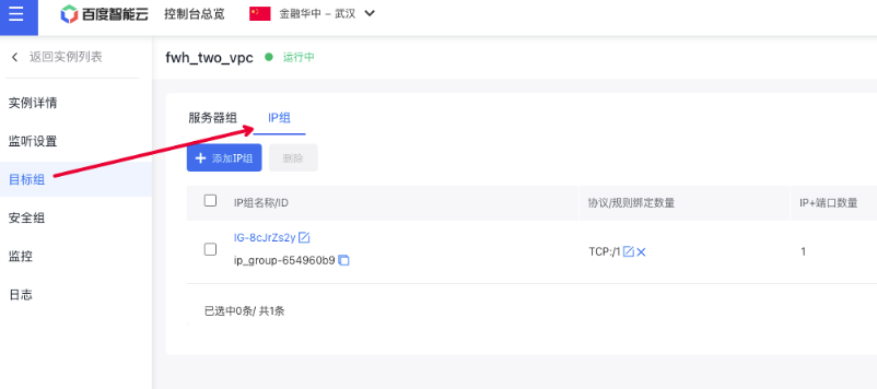
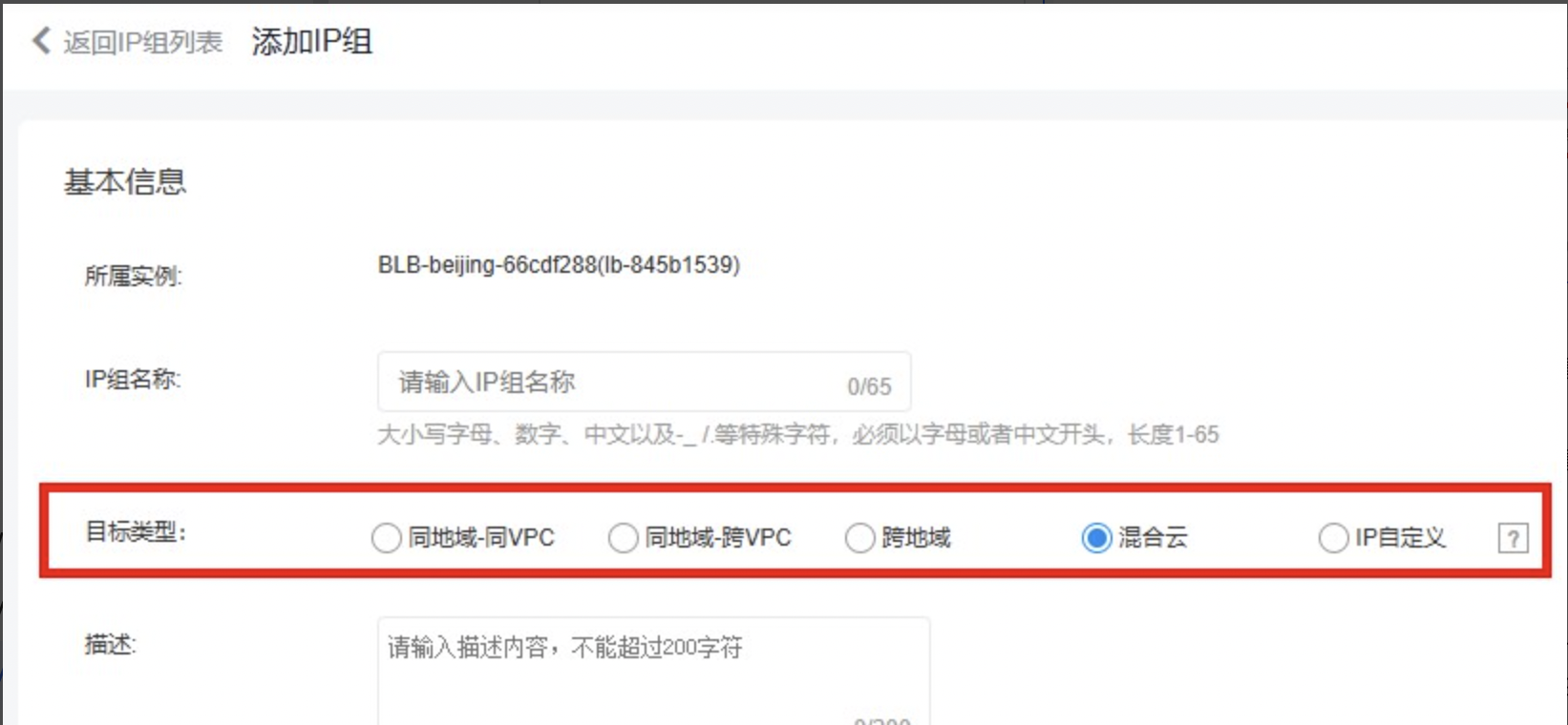
- Note: Below are the definitions for each type.
| Types | Application scenarios |
|---|---|
| Same region - same VPC: | The IP addresses added to the IP group belong to the same VPC as the BLB. This allows mounting of servers like BCC or BBC within the same VPC. |
| Same region - cross-VPC: | The IP addresses added to the IP group belong to separate VPCs from the BLB but can communicate through peering connections. For example, cross-VPC BCC or BBC servers can be mounted. |
| Cross region: | The IP addresses added to the IP group belong to different regions with the BLB, which can be interconnected through peering connections, and the IP addresses are compute-type servers (BCC or BBC) |
| Hybrid cloud: | The IP addresses added to the IP group belong to the same region or different regions with the BLB. For example, it can mount servers in offline IDCs, cross-region server IP addresses in the cloud, cross-region network elements with IP addresses, or cross-cloud accessible IP addresses |
| Custom IP: | If the IP custom type is selected, IP members in the IP group can be configured with the above target types respectively |
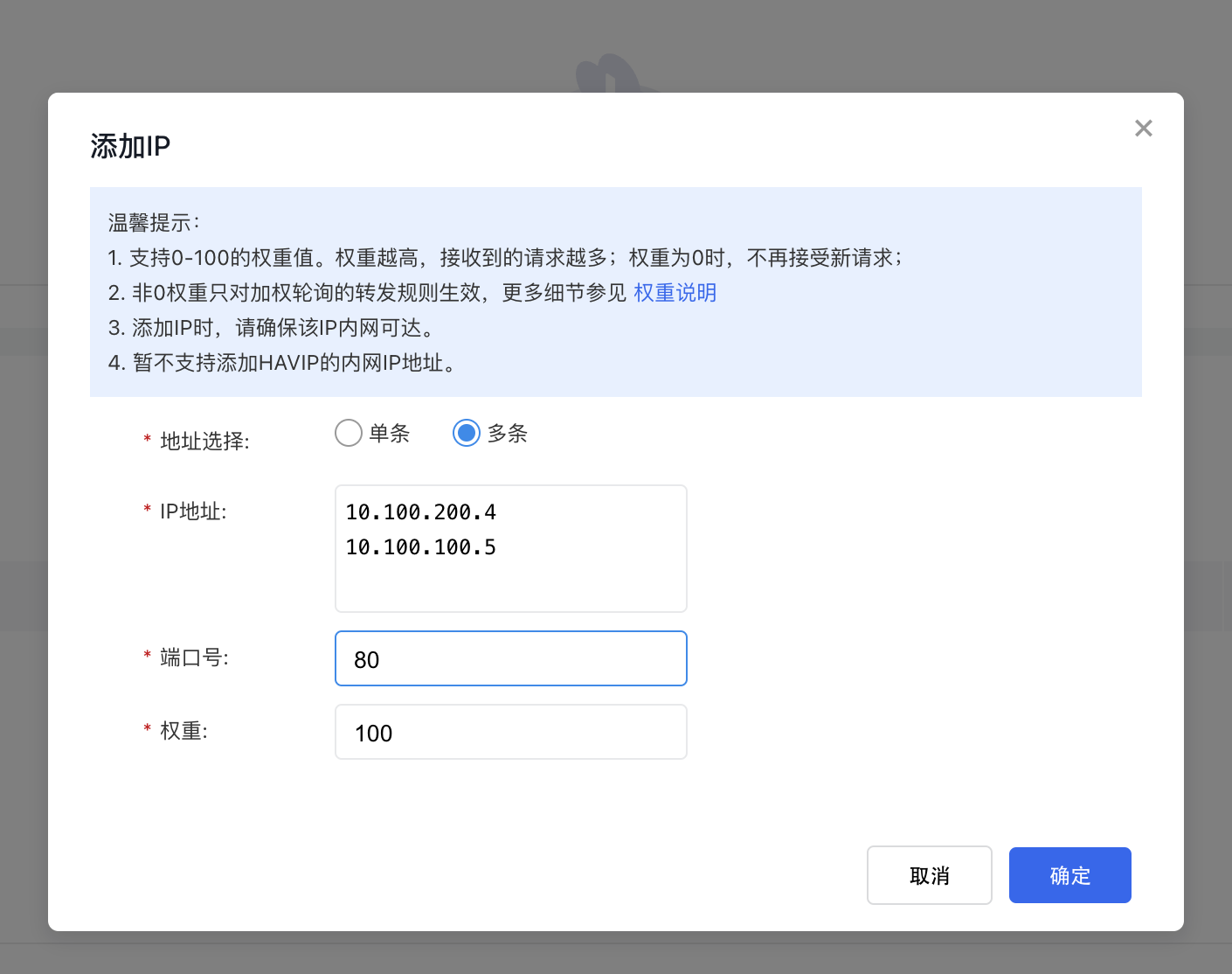
- Mount 10.100.100.5 and 10.100.200.4 as IP group members, with the target type set to cross-region, and add new open protocols.
- Set up the appropriate TCP or UDP listeners in the load balancer and attach the IP group created in the previous step.
Use peering connections to connect VPC1 and VPC2 environments and configure routes
For more instructions on peering connections, please refer to: Peering Connections Description Document After creating the corresponding peering connections, we also need to perform the following configuration:
1. VPC relay route
Ensure relay routing is activated for VPC1 where the BLB resides.
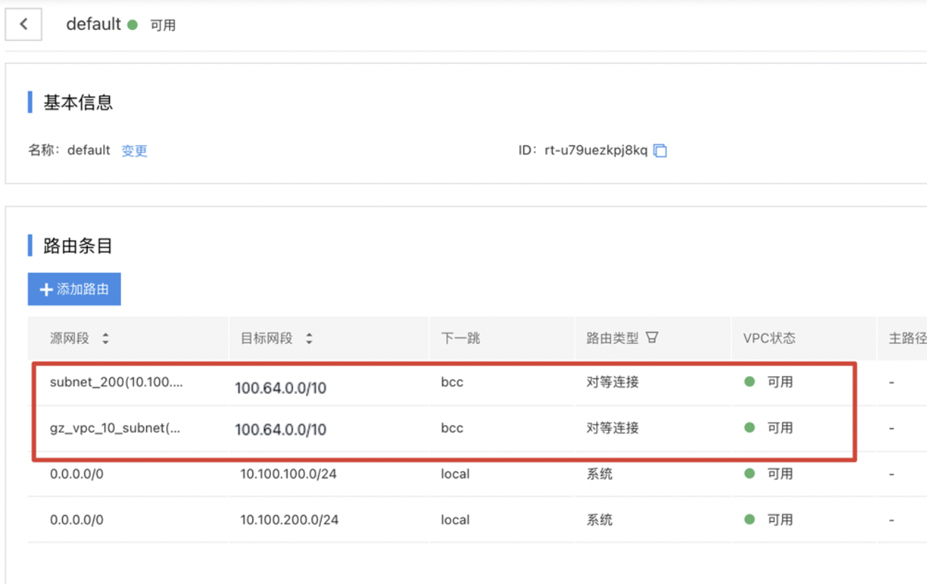
2. Route configuration for VPC1 where BLB resides
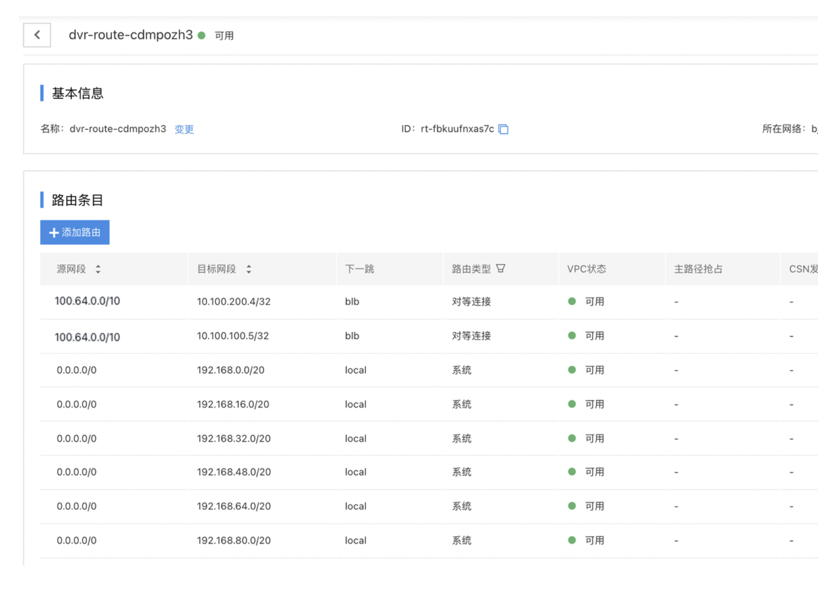
Add a custom route to the route configuration for VPC1 where BLB resides: 100.64.0.0/10->X.X.X.X/32 (real server IP address or network segment).
In this example, we configure 100.64.0.0/10->10.100.100.5/32 and100.64.0.0/10->10.100.200.4/32, with the route pointing to the peering connections end to connect health check route.
3. Route configuration for VPC2 where the real servers reside
In the VPC2 where the real servers reside, add source network segments 10.100.100.0/24 and 10.100.200.0/24 (the address ranges of the real servers) to the route table used by the real servers, with the destination network segment being the load balancer reserved segment (100.64.0.0/10), and with the route pointing to the peering connections end.
 Note: If VPC2 achieves connectivity with VPC1 via peering connections and also establishes connections with VPCs in other regions (e.g., VPC3), while simultaneously serves as the real server for BLBs in these different regions, more granular routing policies are required when configuring the target load balancer address network segments. If needed, submit a ticket to obtain corresponding support.
Test connectivity
Access the load balancer IP 192.168.0.8:80 using a client within VPC1
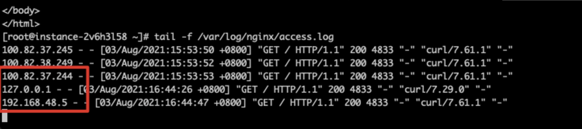
Data stream across regions and VPC is possible.
How to obtain client source IP (CIP)
- For TCP/UDP listeners, the CIP can be directly extracted from the message header in same-region same-VPC, same-region cross-VPC, and cross-region scenarios.
- For cross-region TCP/UDP listeners in hybrid cloud setups, such as scenarios where BLB connects to offline IDCs or cloud-based cross-region servers, the client IP address (CIP) is not visible by default due to multiple NAT conversions across network elements or cross-cloud IP infrastructure. Submit a ticket to gain the necessary support if CIP visibility is required.
- TCP/UDP/TCPSSL-type listeners currently support ProxyProtocol. Users can enable this on the BLB and decode the ProxyProtocol standard protocol on the real server to retrieve the CIP.
- For HTTP/HTTPS-type listeners, CIP passthrough is not currently supported. Users can activate the "Obtain real IP via X-Forwarded-For" option to decode the HTTP header on the real server for CIP retrieval.
Note
- When setting up back-to-origin connections using dedicated lines, ensure that VPC relay routing at both ends avoids routing loops.
- Route rules and load balancer configurations must match the client's actual network segment environment to guarantee connectivity.
- Security groups and ACL settings for each BLB and real server must be correctly configured to prevent unintended blockages and packet loss, which could lead to access failures.